I. Overview
Hydraulic press system mainly includes main oil pump, hydraulic oil tank, filter, pressure reducing valve, relief valve, lifting cylinder, elastic cylinder, clamping cylinder, leg cylinder, hydraulic motor and so on. Hydraulically operated valve. And other parts. Adjust the pressure of the relief valve, pressure reducing valve and various pressure valves before the equipment leaves the factory to ensure the safe operation of the hydraulic press system. Users must not easily change it during use.
The hydraulic press system includes the main hydraulic system and the steering hydraulic system, and the two systems share a hydraulic tank.
1, the main hydraulic system
The main hydraulic press system provides hydraulic power to the rig during equipment adjustment and drilling and repair operations. It is equipped with various valve components to correctly and safely control the operation of each hydraulic tool.
2. Steering hydraulic system
The steering hydraulic press system provides hydraulic power to the hydraulic power steering unit of the front axle of the vehicle. Equipped with a variety of valve components, control the pressure of the hydraulic press system, flow direction and stable flow, to ensure that the vehicle steering light, sensitive, safe and reliable.
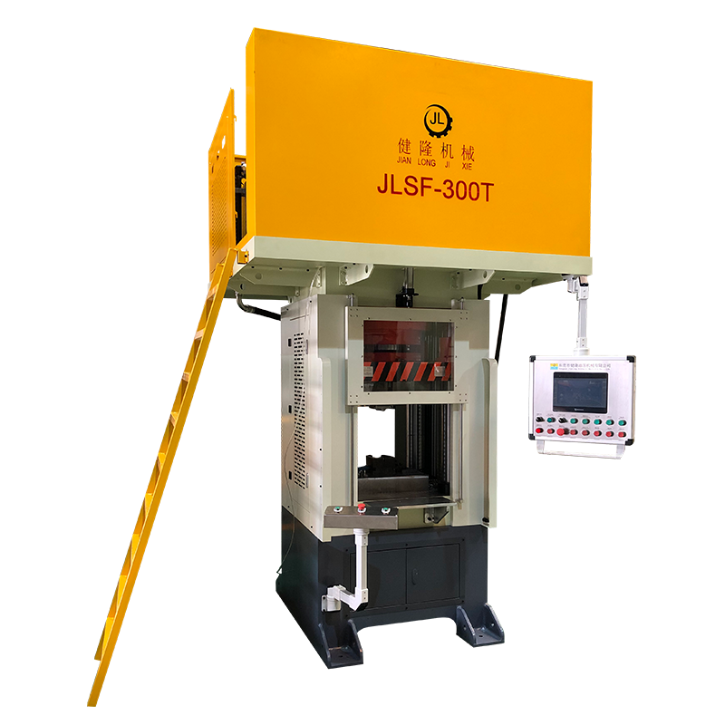
Four-column drawing hydraulic press
Secondly, the structural characteristics
The hydraulic press system consists of the following parts:
̈ main hydraulic system
Steering steering hydraulic system
1, the main hydraulic system
It consists of the following components:
1) Hydraulic tank: Store, cool, deposit and end filter hydraulic oil. Fuel tank equipment includes:
l Manhole cover, the equipment is on the top of the oil tank, there are two, the manhole cover device in the return oil tank area is provided with a hydraulic air filter;
l hydraulic air filter, filter tank air flow, fill the tank filter oil;
l Level gauges, two devices located on the front of the tank, with two level gauges, high gauge, showing the oil level after the derrick is lowered; Low level gauge, showing the oil level after the derrick is erected;
l Oil temperature gauge, the device is located on the front of the tank to measure the oil temperature of the tank, and the normal working oil temperature is 30 ~ 70°C; Two main water return ports, placed on the bottom plate of the water tank, equipped with a check valve, the water outlet is connected with the main water return pipe and the overflow valve return port; The check valve is automatically closed when the hydraulic line is repaired to avoid the loss of oil in the tank;
l The oil outlet is installed on the bottom plate of the fuel tank and plugged with a plug; Open the plug to drain the hydraulic oil in the tank;
l Main oil pump oil suction port, arranged on the front of the oil tank, main oil suction filter device;
Install the oil suction port of the oil pump on the front side of the fuel tank, and turn the device to the oil suction filter;
The oil return port of the return system, placed on the tank bottom plate, is equipped with a check valve, the check valve repairs the hydraulic pipe when the road is closed, to avoid oil loss in the tank;
2) Hydraulic oil pump: single gear structure, 2 sets, the separation equipment is placed on the two hydraulic transmission force box, driven by the torque converter pump wheel, the engine rotation, the power box can drive the oil pump. The power output box is equipped with a hydraulic separation device. When hydraulic pressure is required, the driller can operate the "liquid pump split" handle of the drill box and set the position of "oil pump I", and the oil pump I will output the working pressure oil; Handle set "oil pump II" position, combined oil pump II, output working pressure fluid; The handle is in a neutral position, and neither pump is stalling.
3) Safety valve: pilot structure, 2 sets, separate from the equipment at the outlet of the main hydraulic pump. Set system pressure to avoid system overload and maintain system and component safety.
The relief valve structure principle: by the pilot valve and the main slide valve. The pilot valve part includes a valve body, a slide valve, a pressure regulating spring and other components. The main spool has a small hole A that allows the inlet pressure oil to enter the upper chamber of the spool B. When the hydraulic pressure on the taper valve is lower than the pre-load of the pull spring, the pilot valve lifts the valve to the force in spring. The effect is off. Because there is no oil movement in the valve body, the oil pressure in the upper and lower oil chambers of the slide valve is flat. Therefore, the slide valve is in the limit position of the lower end under the action of the upper spring. The inlet and outlet of the relief valve are blocked by the slide valve, and the relief valve does not overflow; When the hydraulic pressure acting on the taper valve is increased to the spring force corresponding to the increase in the pressure of the relief valve inlet, the taper valve is opened, and the oil in the upper chamber of the spool valve B flows into the oil. The outlet of the valve spills back to the tank through the oil return port b and the center hole of the spool valve. At this time, the pressure oil at the oil inlet of the relief valve passes through hole a. Due to the pressure loss of the oil through hole a to cavity B, the pressure of cavity B is lower than the inlet pressure and the pressure difference between the upper and lower slide valves. Therefore, the pressure difference between the upper and lower pressure heads affects the spring force, the weight and friction of the slide valve itself move upward, open the inlet and return port of the relief valve, the oil flows back to the tank, the slide valve is opened, the liquid power is: the influence of the inlet P pressure continues to rise, the slide valve continues to move upward. When the force of the slide valve is balanced in a certain direction, the inlet pressure of the relief valve is stable at a certain value. This value is called the set pressure of the relief valve. .
4) Oil suction filter: self-sealing structure outside the box, the equipment is located on the side of the hydraulic tank, the suction pipe is immersed in the liquid level of the tank, and the filter head is exposed to the outer tank; There are self-sealing valves, bypass valves, filter contamination polling equipment and other equipment. When replacing or cleaning the filter element, it can be opened outside the box, and the equipment is convenient; In order to control the power failure of the electromagnet, the signal ensures that the pilot valve and the upper cylinder reversing valve are in the middle position, so that the hydraulic press can complete continuous work under the action of force.
From the working principle of the hydraulic press slider, it is not difficult to see the complex and high-quality technical requirements in the manufacturing process of the hydraulic press. Therefore, many people in the industry believe that the price and quality of hydraulic presses are proportional to quality. Of course, this is not unreasonable. So buy a hydraulic press. The time should start from the quality, not only pay attention to the price, but also judge the quality of the hydraulic press from the performance of the hydraulic press slider.
Four column hydraulic press

Contact: Miss.Li
Phone: 18822971180
Tel: 86-18822971180
Email: lifuyan78@gmail.com
Add: Guangyi Industrial Park, No. 2, Tanglip Jinfu West Road, Liaobu Town, Dongguan City, China
We chat
