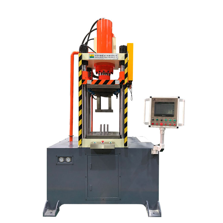
The system mainly includes the main oil pump, hydraulic oil tank, filter, pressure reducing valve, relief valve, lifting cylinder, elastic cylinder, lifting clamp cylinder, leg cylinder, hydraulic motor, and various hydraulic operation valves and other components. The pressure of the relief valve, pressure reducing valve and various pressure valves has been adjusted before the equipment leaves the factory to ensure the safe work of the hydraulic press system, and the user shall not make hasty changes in the use of the machine.
1, the main hydraulic press system
2. Turn to the hydraulic press system
The hydraulic press system consists of the following:
¨ Switch to hydraulic press system
Consists of the following parts:
l Manhole cover, equipment on the top of the oil tank, provided with two, in which the manhole cover in the oil tank return area of the equipment hydraulic air filter;
l Liquid level gauge, 2, the equipment in the front surrounding surface of the fuel tank, provided with convex and convex two liquid level gauges, high level gauges, flash the oil level after the derrick falls; Low level gauge, flash oil level after derrick erection;
l Drain the oil port, which is arranged on the bottom plate of the fuel tank and blocked with a plug; Open the plug to discharge the tank hydraulic oil;
l The oil suction port of the steering pump is arranged on the front surrounding surface of the fuel tank, and the equipment turns to the oil suction filter;
2) Hydraulic oil pump: single gear structure, 2 sets, respectively, the equipment is on the two hydraulic transmission take-up boxes, driven by the torque converter pump wheel, the engine rolls, the take-up box can drive the oil pump. The extraction box is equipped with a hydraulic disperser. When hydraulic action is required, the driller can operate the "liquid pump disperser" handle of the control box, place the "oil pump I in" position, and combine the oil pump I to output the operating pressure oil; The handle is placed in the "oil pump II" position, and the oil pump II is combined to output the operating pressure oil; . The handle is placed in the middle position, and both oil pumps are out of the stall.
The structure principle of relief valve: composed of pilot valve and main slide valve, pilot valve part includes valve body, slide valve, pressure regulating spring and other parts. There is a small hole A on the main valve slide valve, so that the inlet pressure oil can enter the upper chamber of the slide valve B. When the hydraulic force acting on the taper valve is less than the pre-tightening force of the spring, the pilot valve taper valve is closed under the action of the spring force, because there is no oil activity in the valve body, the liquid pressure of the upper and lower oil chambers of the slide valve is equal. Therefore, the slide valve is in the limit position of the lower end under the action of the upper spring. The oil inlet and outlet of the relief valve are blocked by the slide valve, and the relief valve does not overflow; When the liquid pressure acting on the poppet valve increases to equal to the spring force due to the increase of the pressure at the inlet of the relief valve, the poppet valve is pushed open, and the oil in the upper chamber of the spool valve B flows into the oil outlet of the valve through the oil return port b and the central hole of the spool valve, and then spills back to the tank. At this time, the pressure oil in the oil inlet of the relief valve is supplemented upward from the small hole a to the chamber B, because there is pressure loss when the oil passes through the small hole a. Therefore, the pressure of chamber B is lower than the pressure of the oil inlet, and there is a pressure difference between the upper and lower ends of the slide valve. Therefore, under the action of the pressure difference between the upper and lower ends of the spool beat the spring force, the spool weight and friction move upward, open the oil inlet and outlet of the relief valve, the oil flows back to the tank, after the spool is opened, under the influence of hydraulic power, the pressure P of the inlet will continue to rise, the spool continues to move upward, and when the spool is balanced in a certain direction, the pressure of the spool inlet is stable at a certain value. This value is called the set pressure of the relief valve.
5) Return oil filter: equipped with bypass valve and pressure difference indicator, filter solid impurities in hydraulic oil, prevent impurities in the pipeline into the tank, adhere to the system oil clean; Bypass valve, when the filter element is blocked, and can not be stopped immediately for maintenance, the oil can be circulated through the bypass valve, when the stop to clean or replace the filter element; Pressure difference indicator, mechanical visual structure, filter block, affecting oil hydraulic difference, indicating pile protruding, when pointing to the red area, should stop cleaning or replace the filter element.
7) Lifting cylinder: three-level composite cylinder structure, equipped with one-way saving valve; Lifting and lowering the derrick, one-way saving valve to prevent gravity overspeed in the process of lowering the derrick, to protect the safety of the derrick. The machine is equipped with double lifting cylinders.
l Exhaust air: The air in the lifting cylinder and elastic cylinder should be completely discharged before each lifting and landing of the derrick. The hydraulic oil contains air, and the leakage of the pipeline leads to the storage of air in the cylinder. When the lifting cylinder and the elastic cylinder are parked for a long time, the air will be enriched in the upper part of the cylinder. When the derrick is raised and lowered, it will increase the probability of accidents, discharge air, and eliminate the danger of accidents.
l Discharge the air in the rod cavity of the three-stage piston of the lifting cylinder: close the needle valve E, and the lifting cylinder P1 and P3 constitute a closed loop. Gently lift the lifting cylinder control valve handle, supply pressure oil to the lower cavity of the lifting cylinder, the oil pressure is controlled at 2 ~ 3MPa, open the air release plug at the three-stage piston cylinder head of the cylinder, and discharge the air in the lifting cylinder.
Four-column drawing hydraulic press

Contact: Miss.Li
Phone: 18822971180
Tel: 86-18822971180
Email: lifuyan78@gmail.com
Add: Guangyi Industrial Park, No. 2, Tanglip Jinfu West Road, Liaobu Town, Dongguan City, China
We chat
